
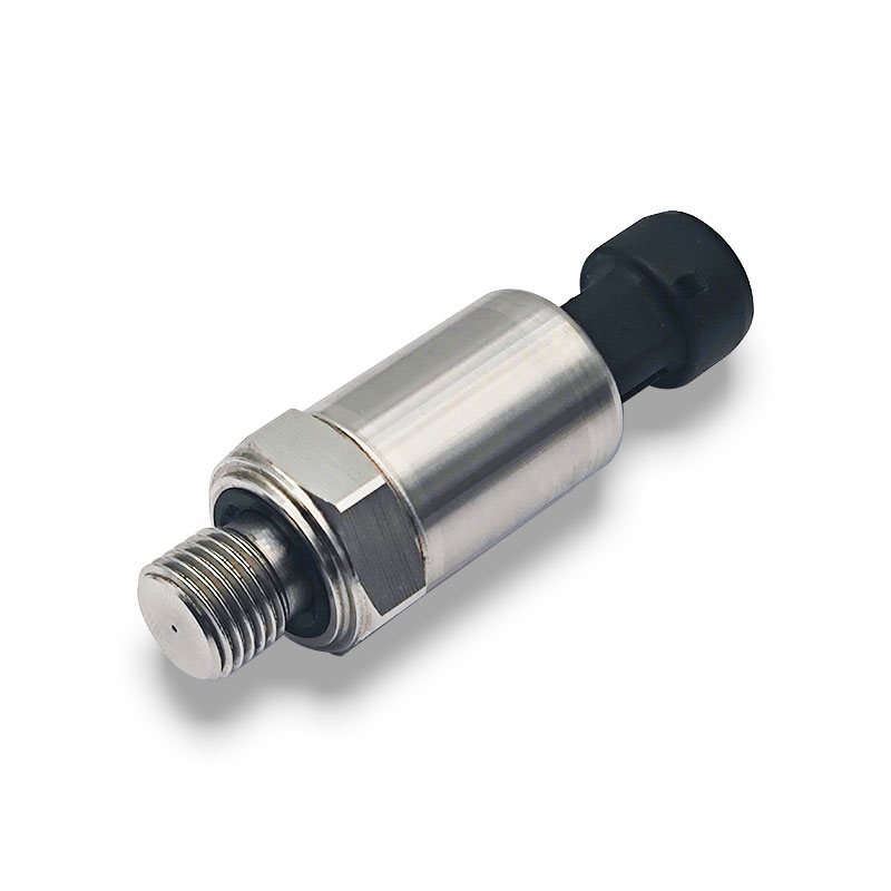
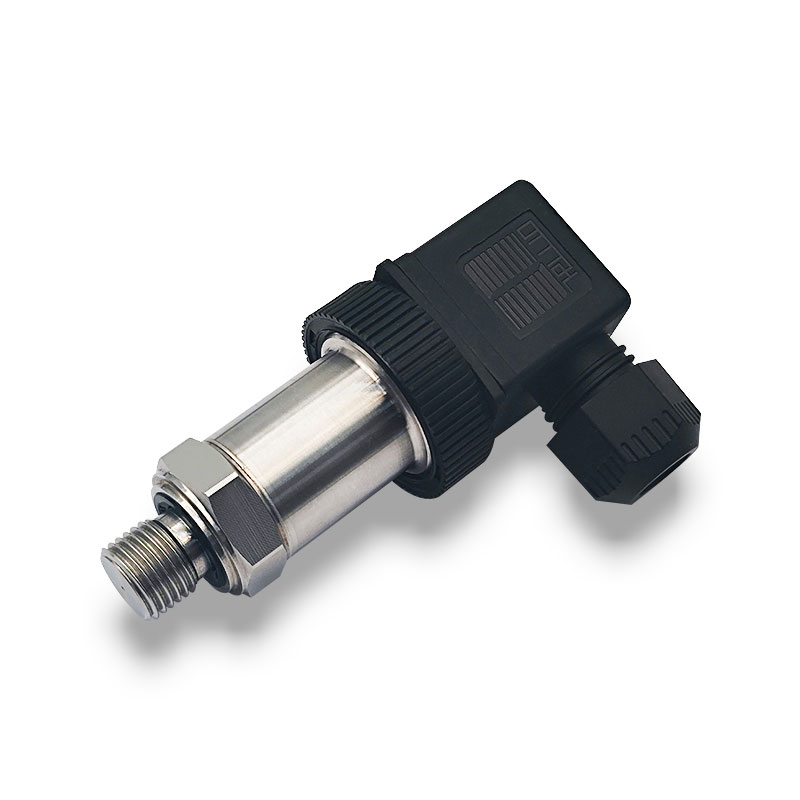


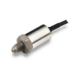
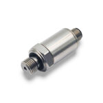
SDP-WP7300 IP68 High-Overload Industrial Pressure Transmitter
The SDP-WP7300 is a compact industrial pressure transmitter designed for air and water applications. Combining IP68 protection with high overload capability, it delivers dependable pressure measurement for water supply systems, water treatment equipment, and hydraulic or pneumatic installations.
An integral pressure cavity minimizes potential leak paths, while reverse polarity and output short-circuit protection support reliable operation. Multiple pressure connections and electrical configurations, gauge and compound pressure options, and an optional pressure snubber provide flexibility for OEM integration.
Features
• IP68 Protection — Designed for demanding environments where moisture protection is essential.
• High Overload Capability — Overload ratings of 5–10 times nominal pressure, depending on the selected configuration.
• Accurate Measurement — Typical accuracy of ±0.25% FS BFSL at 25°C.
• Robust Construction — Compact design with an integral pressure cavity to minimize potential leak paths.
• Flexible Integration — Multiple pressure ports and electrical configurations, with gauge and compound pressure options.
• Built-In Protection — Reverse polarity protection, output short-circuit protection, and an optional pressure snubber.
Product Overview
The SDP-WP7300 is a compact industrial pressure transmitter designed for water and air pressure measurement. Its high overload capability and water hammer impact-resistant design make it suitable for water supply systems, booster pumps, industrial water pumps and air compressors.
An integral pressure chamber minimizes potential leakage paths, while the rugged construction supports demanding operating conditions. Available gauge pressure ranges extend from 0–4 bar to 0–25 bar, with a choice of voltage, current and RS485 outputs.
Pressure connections, electrical interfaces and optional damping can be selected to suit the installation and pressure dynamics of the application.
Product Features
- Designed for water and air pressure monitoring.
- Water hammer impact-resistant design for pump and water supply applications.
- High overload capability, depending on the selected pressure range and configuration.
- Integral pressure chamber to minimize potential leakage paths.
- Gauge pressure ranges from 0–4 bar to 0–25 bar.
- Accuracy: ≤±0.5%FS.
- Voltage, 4–20 mA and RS485 output options.
- IP68 protection available with the appropriate electrical configuration.
- Reverse polarity and output short-circuit protection.
- Optional damping for applications with pressure fluctuations.
Typical Applications
- Building water supply and pressure boosting systems.
- Booster pumps and industrial water pumps.
- Water treatment equipment.
- Air compressors and pneumatic systems.
- Industrial pressure monitoring and control.
Technical Specifications
| Parameter | Specification |
|---|---|
| Model | SDP-WP7300 |
| Product Type | Industrial pressure transmitter |
| Pressure Reference | Gauge |
| Pressure Ranges | Available full-scale ranges from 0–4 bar to 0–25 bar |
| Accuracy | ≤±0.5%FS |
| Voltage Outputs | 0.5–4.5 V, 1–5 V, 0–5 V, 0–10 V or 1–6 V |
| Current Output | 4–20 mA |
| Digital Output | RS485 |
| Operating Temperature | −40°C to +125°C; cable temperature limit: +105°C |
| Compensated Temperature | −20°C to +85°C |
| Storage Temperature | −40°C to +125°C; cable temperature limit: +105°C |
| Long-Term Stability | ±0.5%FS/year |
| Pressure Cycle Life | 10 million cycles from zero to full-scale pressure |
| Insulation Resistance | 100 MΩ minimum at 250 VDC, between signal wiring and housing |
| Supply Voltage | To be specified according to the selected output |
Overload & Water Hammer Resistance
The SDP-WP7300 is designed to withstand transient pressure loads encountered in water systems, including pressure surges caused by pump operation and valve switching. Optional damping can be specified to suit the application.
| Item | Description |
|---|---|
| Overload Capability | High overload design; allowable overload pressure must be confirmed for the selected range and configuration |
| Water Hammer Resistance | Designed for resistance to transient pressure impacts in water systems |
| Damping | Optional |
| Application Selection | Specify normal working pressure, maximum surge pressure and expected pressure cycling |
Electrical Characteristics
| Parameter | Specification |
|---|---|
| Voltage Output Load | RL > 100 kΩ |
| Current Output Load | RL < (Vs − 9 V) / 0.02 A, where Vs is the supply voltage |
| Current Consumption | 10 mA maximum for voltage-output versions |
| Voltage Output Response | <2 ms, 10–90% response, without damping |
| Current Output Response | <3 ms, 10–90% response, without damping |
| Electrical Protection | Reverse polarity protection and output short-circuit protection |
| RS485 Configuration | Confirm protocol, communication settings and wiring before ordering |
Mechanical & Environmental Characteristics
| Parameter | Specification |
|---|---|
| Pressure Chamber | Integral construction |
| Material Options | 17-4PH stainless steel with 304 stainless steel, or integral 17-4PH construction, depending on configuration |
| Ingress Protection | IP68 configuration available; confirm the complete assembly and immersion conditions |
| Mechanical Shock | 50 g, 11 ms half-sine; MIL-STD-202G, Method 213B, Condition A |
| Vibration | ±20 g; MIL-STD-810C, Procedure 514.2-2, Curve L |
| Pressure Connection | Selected according to installation requirements |
| Electrical Connection | Selected according to output and environmental requirements |
Configuration Options
- Pressure range matched to the normal working pressure and expected pressure peaks.
- Voltage, current or RS485 output to suit the control system.
- Pressure connection matched to the equipment interface.
- Electrical connection and cable arrangement matched to the installation.
- Optional damping for pulsating pressure conditions.
- Waterproof configuration for wet operating environments.
Installation Notes
- Verify compatibility between the measured medium and all wetted materials.
- Choose a pressure range suitable for both normal operation and expected pressure surges.
- Apply installation torque at the designated wrench flats and follow the approved installation specification.
- Confirm the supply voltage, output type and wiring diagram before connecting power.
- Observe the temperature limits of the transmitter, cable and electrical connection.
- For outdoor or wet installations, verify the sealing of the complete electrical assembly.
Product Selection
Please provide the following information so SensorDyna can recommend a suitable SDP-WP7300 configuration.
| Selection Item | Information Required |
|---|---|
| Application | Water supply, booster pump, industrial water pump, air compressor or other equipment |
| Measured Medium | Medium type, composition and material compatibility requirements |
| Pressure Range | Required full-scale range and normal working pressure |
| Pressure Surges | Maximum expected surge pressure and frequency of pressure cycling |
| Output Signal | 0.5–4.5 V, 1–5 V, 0–5 V, 0–10 V, 1–6 V, 4–20 mA or RS485 |
| Power Supply | Available supply voltage |
| Process Connection | Thread type, sealing method and installation dimensions |
| Electrical Interface | Connector or cable requirements, cable length and pin assignment |
| Operating Environment | Medium temperature, ambient temperature and ingress protection requirements |
| Additional Requirements | Damping, labeling, documentation and order quantity |
