
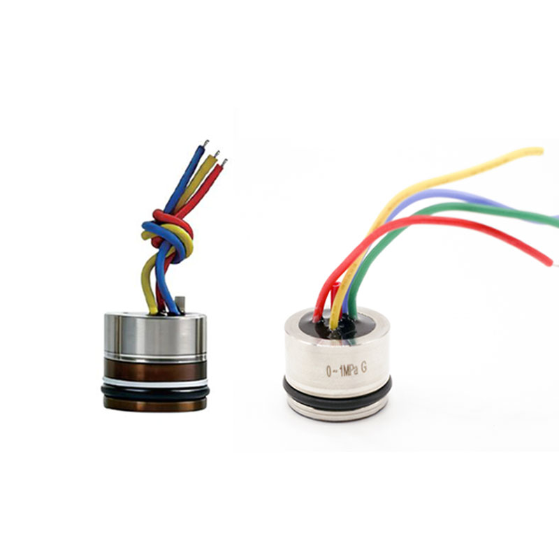
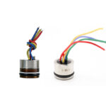

GF200 Glass Micro-Fused Sensing Elements
Pressure interface has no welds exposed to medium, no silicone oil or organic materials, ensuring superior sealing. Sensing elements are firmly bonded to the pressure fitting via glass-bonded silicon strain gauge technology, significantly enhancing high-temperature resistance, vibration tolerance, and Long term reliability. Features high durability with pressure cycle count exceeding 10 million cycles.
Features
Glass-bonded silicon strain gauge sensing element;
integrated construction with no potential leakage path
Φ19 mm pressure sensing element
Wide pressure range
Suitable for harsh environments
Wide pressure range coverage
Strong Proof capability Wide operating temperature range
1. Product Overview
The GF200 is a compact, 19 mm diameter pressure sensing element based on glass-bonded silicon strain gauge technology. Its pressure interface contains no welds exposed to the medium, silicone oil or organic filling materials, providing a robust, oil-free pressure-sensing structure.
The silicon strain gauges are firmly bonded to the pressure fitting using glass-fusion technology. This construction provides resistance to high temperatures and vibration, supporting long-term reliability in harsh industrial environments.
The GF200 is available with a millivolt bridge output or an I²C digital output. The I²C version also provides temperature measurement. Pressure cycling endurance is specified at 10 million cycles from zero to full-scale pressure.
2. Key Features
- Glass-bonded silicon strain gauge sensing technology.
- Compact 19 mm diameter format for integration into pressure instruments.
- No welds exposed to the pressure medium and no silicone oil filling.
- Millivolt bridge output or I²C digital output.
- Integrated temperature measurement with the I²C version.
- Proof pressure: 3 times rated pressure.
- Pressure cycling endurance: 10 million cycles.
- Operating temperature: −40 to +125 °C.
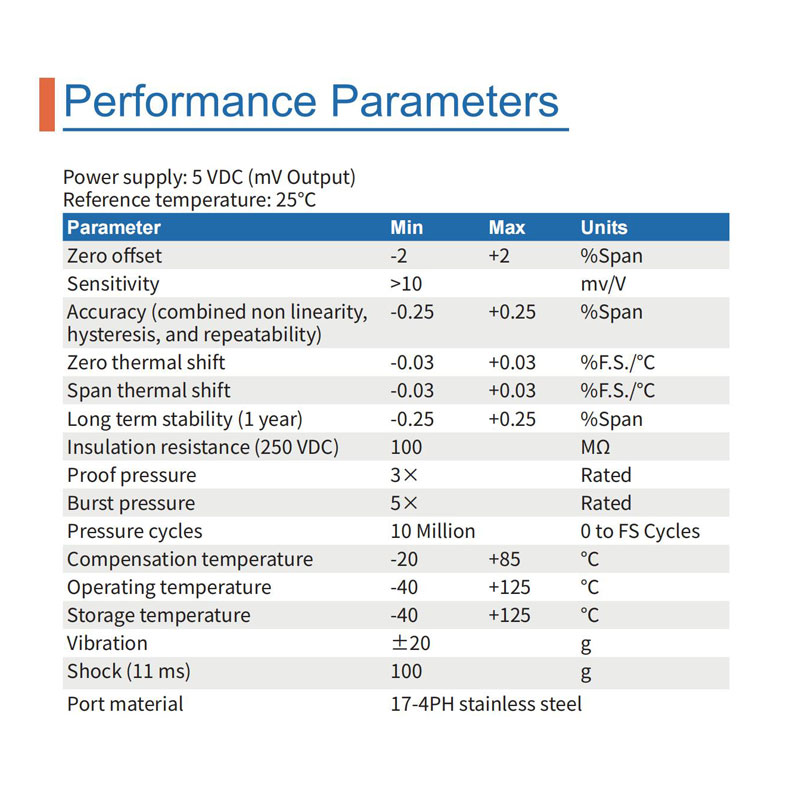
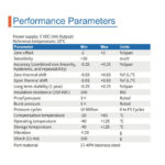
3. Performance Specifications — mV Output
Reference conditions: 5 VDC excitation; ambient temperature of 25 °C.
| Parameter | Specification | Unit / Condition |
| Zero offset | −2 to +2 | % span |
| Sensitivity | >10 | mV/V |
| Accuracy (combined nonlinearity, hysteresis and repeatability) | ±0.25 | % span |
| Zero thermal shift | ±0.03 | % FS/°C |
| Span thermal shift | ±0.03 | % FS/°C |
| Long-term stability (1 year) | ±0.25 | % span |
| Insulation resistance | ≥100 | MΩ at 250 VDC |
| Proof pressure | 3 × rated pressure | — |
| Burst pressure | 5 × rated pressure | — |
| Pressure cycling endurance | 10 million cycles | 0 to full-scale pressure |
| Compensated temperature range | −20 to +85 | °C |
| Operating temperature range | −40 to +125 | °C |
| Storage temperature range | −40 to +125 | °C |
| Vibration | ±20 | g |
| Shock | 100 | g, 11 ms |
| Pressure port material | 17-4PH stainless steel | — |
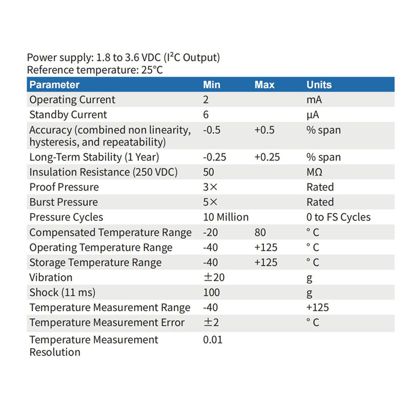
4. Performance Specifications — I²C Output
Supply voltage: 1.8–3.6 VDC.
Reference temperature: 25 °C.
| Parameter | Specification | Unit / Condition |
| Operating current | 2 | mA |
| Standby current | 6 | µA |
| Accuracy (combined nonlinearity, hysteresis and repeatability) | ±0.5 | % span |
| Long-term stability (1 year) | ±0.25 | % span |
| Insulation resistance | ≥50 | MΩ at 250 VDC |
| Proof pressure | 3 × rated pressure | — |
| Burst pressure | 5 × rated pressure | — |
| Pressure cycling endurance | 10 million cycles | 0 to full-scale pressure |
| Compensated temperature range | −20 to +80 | °C |
| Operating temperature range | −40 to +125 | °C |
| Storage temperature range | −40 to +125 | °C |
| Vibration | ±20 | g |
| Shock | 100 | g, 11 ms |
| Temperature measurement range | −40 to +125 | °C |
| Temperature measurement error | ±2 | °C |
| Temperature measurement resolution | 0.01 | °C |
FS = full scale. Span is the difference between the output at full-scale pressure and the output at zero pressure.
5. Electrical Connection
Millivolt output version: Four-wire bridge connection with 5 VDC excitation.
| Wire Color | Designation | Function |
| Red | E+ | Excitation positive |
| Yellow | E− | Excitation negative |
| Blue | S+ | Signal positive |
| Green | S− | Signal negative |
I²C output version: Supply voltage is 1.8–3.6 VDC. Please request the applicable wiring diagram and communication protocol before integration. The mV wiring assignments above do not apply to the I²C version.
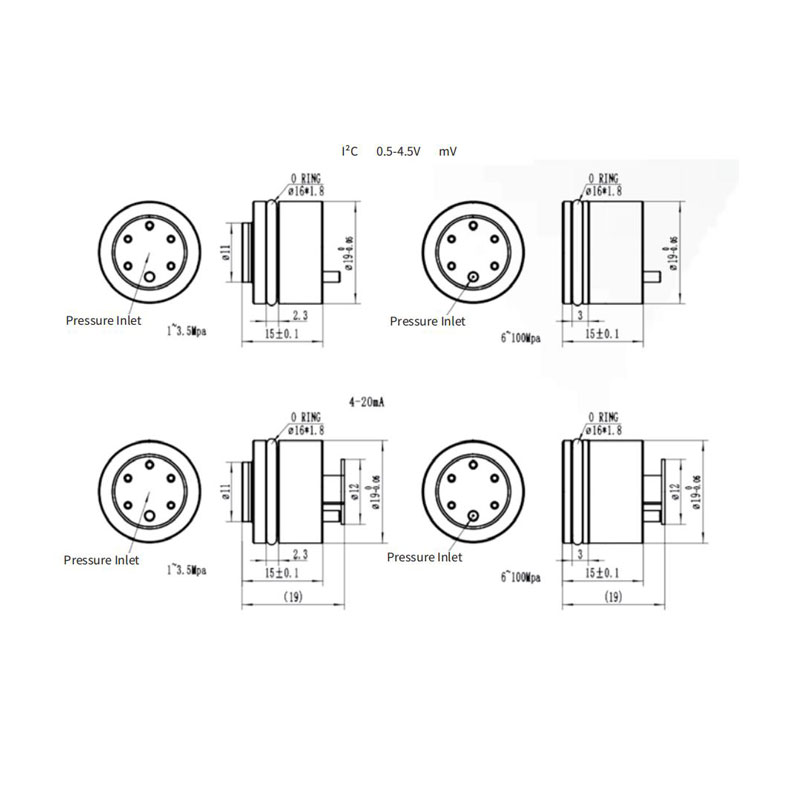
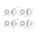
6. Dimensions
The GF200 features a nominal 19 mm diameter format. Separate mechanical drawings are provided for the 1–10 MPa and 25–100 MPa versions. Please confirm the applicable drawing, installation dimensions and sealing arrangement for the selected pressure range.
7. Product Selection
To select a suitable GF200 configuration, please provide the following application requirements:
- Required pressure range and maximum system pressure.
- Output type: millivolt bridge output or I²C digital output.
- Available supply voltage.
- Pressure medium and operating temperature.
- Installation dimensions and sealing requirements.
- Lead wire length and electrical connection requirements.
- Required quantity and any special requirements.
Contact SensorDyna to confirm pressure range availability, media compatibility and the mechanical configuration for your application.
